The groove section shape, pitch and spiral outer diameter of the commonly used spiral concentrator are constant. The inclination angle a of a point on the groove surface along the tangential direction of the groove is called the longitudinal inclination angle, and the tangent of the longitudinal inclination angle is equal to the ratio of the pitch to the circumference of one turn of the point, that is: where: t——pitch; r——the surface of the spiral groove A radius from the axis of rotation. It can be seen that the longitudinal inclination increases as the radius of a point on the groove surface decreases. In the vertical transverse section of the spiral groove, the angle between the tangent to a point at the bottom of the groove and the horizontal plane is called the lateral inclination. The transverse dip system increases with increasing radius. The longitudinal inclination and the lateral inclination jointly determine the maximum inclination y of the transverse plane of the point, and the relationship therebetween is. The direction of the r angle is always biased toward the inner edge of the groove, which is an important factor affecting the direction of the movement of the underlying ore. The slurry in the spiral groove flows along the groove under the action of gravity component, and at the same time it is expanded by the inertial centrifugal force to the outer edge. Thus, a flow characteristic in which the inner edge stream layer is thin, the flow velocity is low, the outer edge flow layer is thick, and the flow velocity is high is formed. According to the measurement, the thickness of the liquid near the inner edge is only 2 to 3 mm, which is a laminar flow state. The thickness of the flow layer near the outer edge is 7-16 mm, and the flow velocity is 1.5-2 m/s, showing a distinct turbulent flow regime. The amount of water fed in is increased, and the wet period is outwardly expanded, but has little effect on the flow characteristics of the inner edge. Figure 11.7.3 shows the results of measurement with water. In addition to flowing in the longitudinal direction of the tank, there is also a lateral exchange between the inner edge fluid and the outer edge fluid. It is called the secondary circulation, as shown in the figure below in Figure 11.7.4. Due to this circulation movement, the rising sub-speed occurs in the inner ring (area A) of the groove, and the outer ring (area B) has a falling sub-speed. The superposition of the longitudinal flow of the liquid stream and the secondary circulation results in a spiral motion of the liquid flow on the groove surface. The upper layer tends to the outer edge and the lower layer tends to the inner edge (as shown in the figure below in Figure 17.7.4).


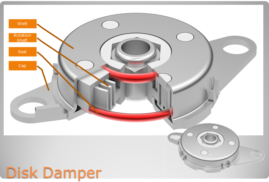
Flat disk Rotary Damper mainly used for large diameter, small height space. Disk dampers provide energy absorption and rotational deceleration. We offer many different models from mild to extreme. Our disk dampers are the perfect solution for a wide range of applications, from scanner, and glove boxes to auditorium seating to. Disk dampers are designed to control and smooth out the opening and closing of lids, and doors.
Our damper is conducive to performing structural movement in soft, silent and safe environment, mitigating impact load, avoiding strike damage, prolonging mechanical life, reducing noise disturbance, improving product quality and improve customer satisfaction.

NOTE:
1. Please contact the corresponding product engineer for specific torque products.
2. Max. rotation speed: 50r/min
3. Max. circle rate: 6 cycle/min ( Clockwise360 °, 360 ° anti-clockwise for 1 cycle)
4. Operating temperature: -10~50℃
5. Storage temperature:-30~80℃
| NO. | Description | Material |
| 1 | Shell | SPFC |
| 2 | Cover | SPFC |
| 3 | Shaft | PA/POM |


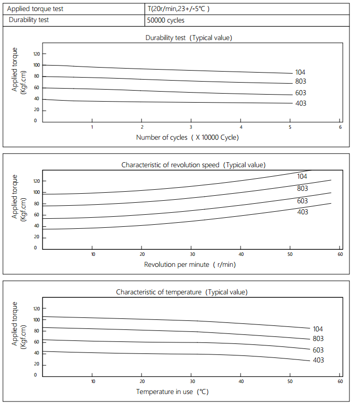
Applied torque:(T)
Test Temperature: 23+/-5℃
Rotating speed: 20r/min
Durability test Metho: Clockwise 360 °, 360 °anti-clockwise
Rotating speed: 20r/min
Test Frequency: (1cycle/min)
Test Temperature: 23±5℃
Durability test cycle: 50000 cycle
Test result criteria: Store in the room temperature for 24 hours or more after the test, recording to the torque T=T±30%T.

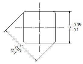
The damper square hole coordinateswith the rotation axis dimension tolerance.
Disk Damper,Adjustable Dampers,Excavator Disk Damper,Spare Disk Damper,Oval Disk Damper
Shenzhen ABD Equipment Co., Ltd. , https://www.abddamper.com