In tobacco products, in addition to tobacco leaves can be processed tobacco, the processing process can produce a large number of stems can also be used in the process of tobacco stems need to remove impurities, restore flexibility, in order to facilitate stem cutting processing, the process requires stem rejuvenation . Sink type stem stem rejuvenation machine is a main equipment on the stem treatment line. It uses the circulating constant water temperature medium to sterilize stems. The equipment is mainly composed of four parts: washing box body, piping system, conveyor belt and moisture control. The entire moisture process control is mainly controlled by the water temperature, the residence time in the stem water, and the amount of compressed air to control the moisture to achieve the process requirements.
According to the needs of equipment work, we design a PLC based on DOP man-machine interface, the pedestal washing machine control system must ensure that the washing machine water reaches the technical requirements, the system DOP man-machine interface as a touch screen, using S7-300PLC as the control host, Composition of the control system, the composition of the system can complete the water temperature analog closed-loop control, water level digital closed-loop control, circulating water flow rate can be adjusted open-loop control, upstream and downstream water level interlock control. The stable operation of the system ensures high control accuracy and satisfies the system process requirements.
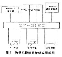
1. Hardware composition of the control system The hardware system of the pedestal washing machine is mainly composed of four parts. The first part is the man-machine interface. The system selects the DOP-AE80THTD touch screen of Zhongda Dentsu, and the AE80 touch screen has 65536 colors and 32-bit RISC microprocessors. , 32M memory, 512K power off, USB programming. There are three serial communication ports, RS232/RS422/RS485 three kinds of communication interface to choose from, consider that we use S7-312C direct communication, we use RS485 interface, touch screen to complete the system display and control and system control parameter adjustment, temperature trend Figure, fault alarm and other tasks. The second part of the process control part of the PLC completed by the S7-312-5BOO-OABO, it has 10 digital inputs, a digital output, to meet the system's digital needs, in addition to the CPU312C need to configure a configuration through the hardware Analog input module 6ES7331-7KFO2-OABO, it is 8-channel 12bit analog A / D conversion module, 12-bit control accuracy can meet the requirements of this system, 8-channel input can be configured to 3-channel temperature platinum resistance PT100 input, 0 ~ The 10V voltage input is used to input the speed signal to the inverter, and the water flow rate is displayed through the conversion amount. An analog output module 6ES7332-5HB01-OABO, which is a 4-way 12-bit analog output module system all the way to output 4 ~ 20mA control pneumatic diaphragm control valve, through the valve opening control tank temperature is constant. The third part is the system input detector, the digital input completes the basic start-stop interlock and water level control. Analog input temperature detection, by the pTl00 sensor complete 3 temperature signal detection, water supply tank temperature closed-loop control. All the way to the voltage input, input frequency converter output frequency, the system is converted into a digital signal for the touch screen display water flow speed. The fourth part is the actuator, which mainly controls the upstream and downstream interlocking output signals of the system, and the water frequency converter starts and stops. The water solenoid valve controls the water level, and the water heating solenoid valve controls the inlet water temperature. Insulation pneumatic diaphragm control valve to complete the temperature control of the tank temperature. The specific composition is shown in Figure 1.
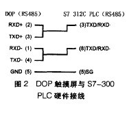
2, DOP touch screen and Siemens PLC communication Siemens S7-312CPLC communication port only MPI interface, does not have a standard RS232 and RS485 interface, usually the touch screen only connects Siemens own touch screen, with its own MPI interface, but Siemens touch screen prices are higher, sometimes Check the system cost-effective, use other brands, so that communication protocol settings require more technology, usually using Siemens PC-MPI adapter cable connection, so simple and reliable but costly, hardware installation of multiple conversion boxes, installation is not convenient. This system uses direct connection, protocol setting is especially important, the specific setting process is as follows: First communication rate: 19200, 8, EVEN, 1. (RS485); then PLC station number: last control area / status area: DBWO/DBW20 . Note that this drive can only be used for 1 DOP HMI with 1 PLC; PLC communication speed needs to be changed to 19200, (8, EVEN, 1.); can not use 2 communication ports are used; DOP station The number must be set to 0 to 15. If this number is exceeded, the communication protocol is automatically changed to 15; when the cable is not connected, an error message is displayed after about 5 seconds of the DOP display unit. If the connection cable is connected, the DOP HMI needs to be re-powered to be able to connect to the communication successfully; after the power transmission, the DOP needs to be notified by the PLC before being connected. Therefore, the time required for the first connection is long. In normal circumstances, it should be connected within 5 seconds. This protocol is a multi-segment round-trip communication (1 command requires DOPHMI to communicate with the PLC several times before it can be completed). Therefore, the communication speed is slower than the general controller. However, the PCadapter speed is basically the same as that of the S7-300. Specific DOP touch screen and PLC hardware wiring as shown in Figure 2.
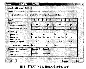
3. Design of analog module 3.1 Setting of analog module In the moisture control part of the washer, select SM331. The analog input module converts the analog signal into a digital signal for internal processing of the CPU. The main component is A/D. converter. General simulation by the transmitter output standard DC voltage, DC current signal. The SM331 can be directly connected to a temperature sensor without a transmitter. This eliminates the need for a temperature transmitter, which not only saves hardware costs but also reduces the number of points of failure. However, connecting the sensor directly requires setting the measurement range. The input type of the S7331-7KFO2-OABO analog module is set using the range card on the side of the module. The range card is installed on the side of the analog module, one set for each two channels, and four channels for eight channels. When set to temperature, two channels are one input. It is usually set at the default B position (±10V) when delivered. Need to set 3 temperature detection, according to data A for temperature sensor input. Therefore, using a screwdriver, loosen the range card from the analog input module, and then position the range card to position A to point to the module and insert the range card. The system sets three range cards as A and the fourth block remains as B. This completes the range card settings for three-way temperature and two-way voltage input. After the hardware is set up, you need to go online to select the analog range in the hardware settings in STEP7. The specific analog input module range setting in STEP7 is shown in Figure 3.
3.2 Analog value module conversion, cycle and response time conversion time consists of basic conversion time and module testing and monitoring processing time. The basic conversion time depends directly on the conversion method of the analog input module (integration method, instantaneous value conversion). The scan time of the analog input channel, that is, the time that the analog input value is converted to the next conversion, refers to the sum of the conversion times of all the active analog input channels of the analog input module. The conversion time of the analog output channel consists of two parts: the time when the digital value is transferred from the CPU memory to the output module and the digital-analog conversion time of the analog module. The analog output channel is also a sequential conversion, that is, the analog output channels are sequentially converted. The scan time, ie the time elapsed for the analog output value to be converted again this time, refers to the sum of the conversion times of all active analog output channels of the analog output module, so you can disable all unused ones in STEP7. Analog channels to reduce I/O scan time.
3.3 Connecting Sensors to Analog Inputs Depending on the method of measurement, we can connect different types of sensors such as voltages or resistors to analog input modules. To reduce electromagnetic interference, shielded twisted-pair cables should be used for analog signals, and the shield of the analog signal cable should be grounded at both ends. If there is a potential difference between the two ends of the cable, an equal potential coupling current will be generated in the shield, causing interference to the analog signal. In this case, one end of the shield of the cable should be grounded. For isolated analog input modules, there is no electrical connection between the M terminal of the CPU and the measurement circuit reference point MANA (typically terminals 10 and 11). If there is a potential difference UISO between the reference voltage UN and the M terminal of the CPU, an isolated analog input module must be selected. By using an equipotential bonding conductor between the MANA terminal and the M terminal of the CPU, you can ensure that UISO does not exceed the permissible value. If the sensor used is a non-isolated sensor, a finite potential difference UCM (common mode voltage) can occur between the measurement line M- of the input channel and the reference point MAA of the measurement circuit. In order to prevent exceeding the permissible value, equal potential connection wires must be used between the measuring points.
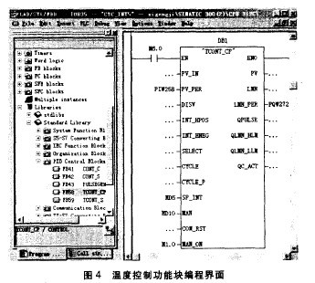
4, temperature control program function block design STEP7 program allows online and offline editing program, first create OB1 system organization block, and then create a timed interruption of the organization block OB35, call the temperature control function block FB58 in OB35, call FB58 premise is installed in STEP7 Standard Library, the calling process is to open OB35 → click View → click Overview → click on the right Library → click on StandardLibrar → click on PIDControlBlocks → click FB58 temperature control function block, enter the background database DB1 when input parameters. DB1 as OB35 background database, the data structure in the background database is automatically generated by the system, the user can not be modified, must enter the data according to the data format requirements in the standard library, there are some system control parameter settings in the background database, some control parameters Can also be modified in the background database, open the background database DB1, select the parameter view, you can modify parameters such as: sampling period, PID parameters, upper and lower limits, pulse output.
Call FB58 function in OB35, input response control quantity, digital quantity and analog quantity. When the parameter input is completed, the system can run the program. There are more than a dozen inputs in the program call LAD display, you can select the necessary input, some must be input, and some can use the system default value. After the system starts up, it will output M6.0 and start FB58. The setpoint variable SP_INT is required for floating-point format input. The input data MW2, MW2 are converted into floating point number MD6 in the touch panel, MD6 is used as SP_INT, and PV_PER (peripheral process control variable) is used as input for the process variable input peripheral equipment (I/O Format variable, that is, the digital value of PIW258 of S7-331-7KF02 analog input module is used as the process variable. If this data is converted into floating-point number, PV_IN can be input, and the PV_IN and PV_PER input in the ladder diagram is 1 However, inputting PV_PER is simple and reduces the writing of the conversion control program. In the control function block, PV_PER is generally input. In the function block, PV_PER is converted into floating point PV_IN, and PV_IN is subtracted from the set value SP_INT is the error. Participate in PID control in the system. Function blocks also have manual functions. When the external conditions do not meet the automatic working conditions, manual control can be used. Specifically, MAN_ON is set to M1.O. When M1.0 is 1, the touch screen can be set to manually output data. MD10, set the MAM to MD10, the LMN_PER process output directly outputs the control value.
The controller has 7 outputs which can be used as the system control output and display output. Among them, the PV format process variables are mainly used and can be used as the steam control valve opening display. LMN_PER is the I/O format control output value, which is output directly to PQW272 and outputs 4~10mA control pneumatic diaphragm control valve at the analog output. The function module also has QLMN_HLM and QLMN_LLM upper and lower limit alarms. This function block programming is basically completed. The temperature control function block programming interface is shown as in Fig. 4.
5. Conclusion DOP man-machine interface is beautiful, with intuitive graphical interface, simple operation, easy to use, the complex production line monitoring has become simple and clear, greatly reducing the labor intensity, production practices in the control system of the pedestal washing machine shows that Various functions of the system meet production needs and increase production efficiency. The automatic control system for the water temperature of the cut stems was completed using the DOP man-machine interface to ensure that the water content of the cut stems was within the acceptable range.
We have got CE certificate from 2015. We make can manufacture various types of high mast with lifting system for stadium highway parking lot and etc.
Our firm introduced whole set of good-sized numerical control hydraulic folding equipment(1280/16000) as well as equipped with a series of good-sized professional equipments of armor plate-flatted machine, lengthways cut machine, numerical control cut machine, auto-closed up machine, auto-arc-weld machine, hydraulic redressing straight machine, etc. The firm produces all sorts of conical, pyramidal, cylindrical steel poles with production range of dia 50mm-2250mm, thickness 1mm-25mm, once taking shape 16000mm long, and large-scale steel components. The firm also is equipped with a multicolor-spayed pipelining. At the meantime, for better service to the clients, our firm founded a branch com. The Yixing Jinlei Lighting Installation Com, which offers clients a succession of service from design to manufacture and fixing.
Steel Lighting Pole High Mast,30m High Mast Pole, High Mast pole for stadium
Jiangsu Xinjinlei Steel Industry Co., Ltd. , https://www.steel-pole.com